Roof
Perimeter and termination conditions where the roof edge needs to stay weather-tight.
Phase 2 knowledge base
This page gathers the most common envelope transition conditions into one grouped library so estimators and spec reviewers can understand the failure modes before they ask for a fabrication quote.
Reference-only detail. Confirm final dimensions, attachment, and code/manufacturer requirements for the project condition. Need a quote? Use /quote/, call 647-407-0171, or email info@canadianmetalfab.com.
The page is organized so estimators can find the condition family first, then read the warning signs before a quote discussion.
The goal is to help a buyer understand the condition, purpose, failure mode, and fabrication fit of each detail. These are original conceptual diagrams, not stamped project drawings or copied manual pages.
Perimeter and termination conditions where the roof edge needs to stay weather-tight.
Transitions where roof water meets a wall, parapet, or projection and needs a clean path.
Drainage conditions that collect runoff and move it through a shared channel.
Reference-only detail. Confirm final dimensions, attachment, and code/manufacturer requirements for the project condition.
Perimeter and termination conditions where the roof edge needs to stay weather-tight.

Perimeter roof termination where runoff needs a clean break from the edge.
Direct water away from the eave and protect the edge of the assembly.
A weak kick, poor fastening, or undersized overhang leaves water tracking back toward the fascia.
Commonly formed from 24-26 ga coated steel or stainless when extra durability is required.
Best handled as a project-specific formed trim with the correct hem, leg depth, and drip geometry.
Reference-only detail. Confirm final dimensions, attachment, and code/manufacturer requirements for the project condition.

Sloped roof edge at the rake where wind and rain can load the trim line.
Protect the exposed edge and create a durable finish at the roof perimeter.
Fastener spacing or profile mismatch can leave the edge looking loose or vulnerable to wind uplift.
Often specified in 24-26 ga steel or heavier when the exposed edge is long or highly visible.
Custom lengths and profiles help the rake read cleanly against the panel system.
Reference-only detail. Confirm final dimensions, attachment, and code/manufacturer requirements for the project condition.

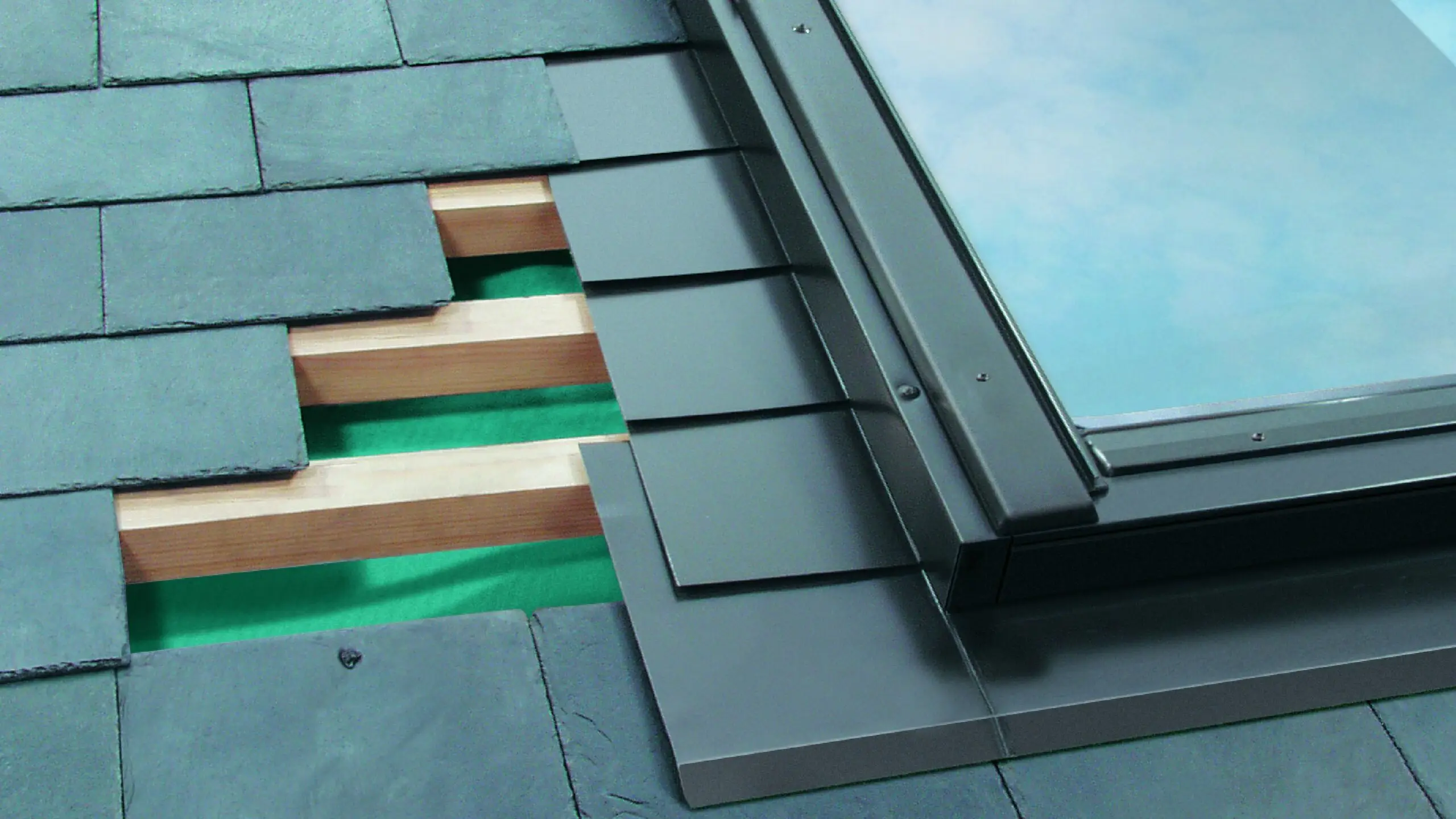
Roof opening or curb where equipment, vents, or another projection interrupts the surface.
Transition water around the opening cleanly and keep the curb perimeter in control.
Poor sequencing between curb flashing and counterflashing leaves the opening vulnerable to leaks.
Thickness depends heavily on curb height, exposure, and whether the part is visible from grade.
Custom curb flashings and pans are a strong fit when the opening geometry is defined early.
Reference-only detail. Confirm final dimensions, attachment, and code/manufacturer requirements for the project condition.
Transitions where roof water meets a wall, parapet, or projection and needs a clean path.

Roof plane running into a vertical wall along the side of the building.
Move water at the roof-to-wall transition and keep the wall line dry.
Short laps, missing counterflashing, or awkward sequencing can trap water at the joint.
Usually formed from 24-26 ga sheet, with heavier material if the wall is exposed or highly visible.
Fabricated step or continuous trim sections should match the wall interface and job sequencing.
Reference-only detail. Confirm final dimensions, attachment, and code/manufacturer requirements for the project condition.

Upslope roof plane terminating into a wall or projection at the high end of the run.
Carry water away from the wall and keep the termination line from backflowing.
An undersized apron or poor lap path lets water pool at the upslope termination.
Often similar to sidewall flashing, but geometry and leg lengths usually need a custom review.
Project-specific bends and lengths make this a strong fit for fabricated sheet metal.
Reference-only detail. Confirm final dimensions, attachment, and code/manufacturer requirements for the project condition.

Upper protective flashing covering the top edge of a base flashing or reglet.
Hide and protect the attachment line and help keep the base flashing watertight.
Poor substrate attachment or a bad sealant interface can defeat the detail quickly.
Typically a moderate-gauge trim piece, but masonry, panel, and curb conditions can call for different stiffness.
Formed counterflashing can be built for masonry reglets, panels, or curb conditions with clean returns.
Reference-only detail. Confirm final dimensions, attachment, and code/manufacturer requirements for the project condition.

Top of parapet wall where the wall needs to be capped and shed water both sides.
Cap the wall, drain water away, and keep the parapet edge from absorbing runoff.
Flat coping, weak joints, or loose splices can create leak paths and movement issues.
Often heavier than edge trim, especially on long runs or when wind exposure is significant.
Coping lengths, splice strategy, and cleat compatibility should be planned together before release.
Reference-only detail. Confirm final dimensions, attachment, and code/manufacturer requirements for the project condition.
Drainage conditions that collect runoff and move it through a shared channel.

Low-side intersection where two sloped roof planes direct runoff into the same channel.
Collect and carry water through the valley without letting it spill into the assembly.
A valley that is too narrow or poorly lapped can overload the drainage path during heavy rain.
Can be formed in 24-26 ga steel or thicker where the valley is long, visible, or load-bearing from runoff.
Long formed valley sections and controlled width choices make fabrication fit the actual roof geometry.
Reference-only detail. Confirm final dimensions, attachment, and code/manufacturer requirements for the project condition.
Typical gauge and material guidance for common flashing conditions. Confirm final specs against the project condition and manufacturer requirements.
| Category | Typical spec | Fabrication note |
|---|---|---|
| Roof edge / drip edge gauge | 24–26 ga coated steel | Lighter gauges suit low-exposure conditions. Increase to 22 ga for long runs or high wind. |
| Wall and parapet gauge | 22–24 ga coated steel | Longer coping and counterflashing runs benefit from stiffer material to hold profile. |
| Valley flashing gauge | 24–26 ga steel or heavier | Match gauge to drainage load and visibility. Heavy runoff valleys may require 22 ga. |
| Aluminum alternative | 0.040–0.063 in | Worth specifying when weight reduction, anodize color match, or galvanic isolation is required. |
| Stainless alternative | 22–26 ga | Specified for extended durability or aggressive corrosion exposure. |
| Lap length | 4–6 in minimum | Confirm with the roofing manufacturer for warranty compliance. |
| Sealant placement | Upslope side of laps | Never fully embed. Leave the downstream edge open to allow drainage. |
Values are reference ranges only. Final gauge, material, and lap call-outs require project-specific review.
These are the questions estimators and spec reviewers most often ask before a fabrication discussion.
Base flashing runs along the roof-to-wall transition and manages water at the surface. Counterflashing sits on top and covers the attachment edge of the base. The two pieces work together as a layered system — each doing a different job.
24 to 26 gauge coated steel covers most conditions. Longer runs, exposed parapets, or high-wind zones may call for 22 gauge or heavier to keep the profile rigid over the life of the installation.
Short laps, inadequate attachment, and sealant applied in the wrong location account for most failures. Thermal movement that was not accounted for in long coping or valley runs is a common secondary cause.
No. These are conceptual reference details. Final dimensions, lap lengths, attachment patterns, and code compliance all require project-specific drawings or manufacturer documentation.
Not usually. Base flashing and counterflashing have different leg depths, returns, and attachment requirements. Custom fabricating each piece to match the actual condition is almost always the correct approach.
Galvanized steel is the practical default for most commercial flashing. Aluminum becomes worth considering when weight matters, when a specific anodized color is required, or when galvanic isolation is already built into the assembly design.
Send the roof, wall, or valley condition through the existing quote flow when you want fabrication-minded input. It keeps the next step low-pressure while still giving the detail a real project review.
Use /quote/ for the cleanest handoff, or email info@canadianmetalfab.com if that is easier.
For quick contact, use /quote/, call 647-407-0171, or email info@canadianmetalfab.com.